Building a Custom Game Boy with the ESP32-S3

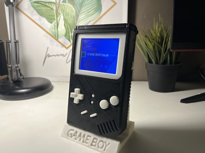
Over three months I built a fully working handheld retro console from scratch — wiring, firmware, and enclosure — around the ESP32-S3-N16R8. Every subsystem was hand-assembled: point-to-point wiring on perfboard, off-the-shelf modules, a hand-soldered input board, and a 3D-printed shell. The firmware required porting Retro-Go — an ESP-IDF multi-emulator launcher — to a target it was never written for, which meant writing a full config.h from scratch across multiple iterations to get every pin, bus, and display register right. The project earned Third Place in the Engineering Track at NU UGRF 20th Edition.

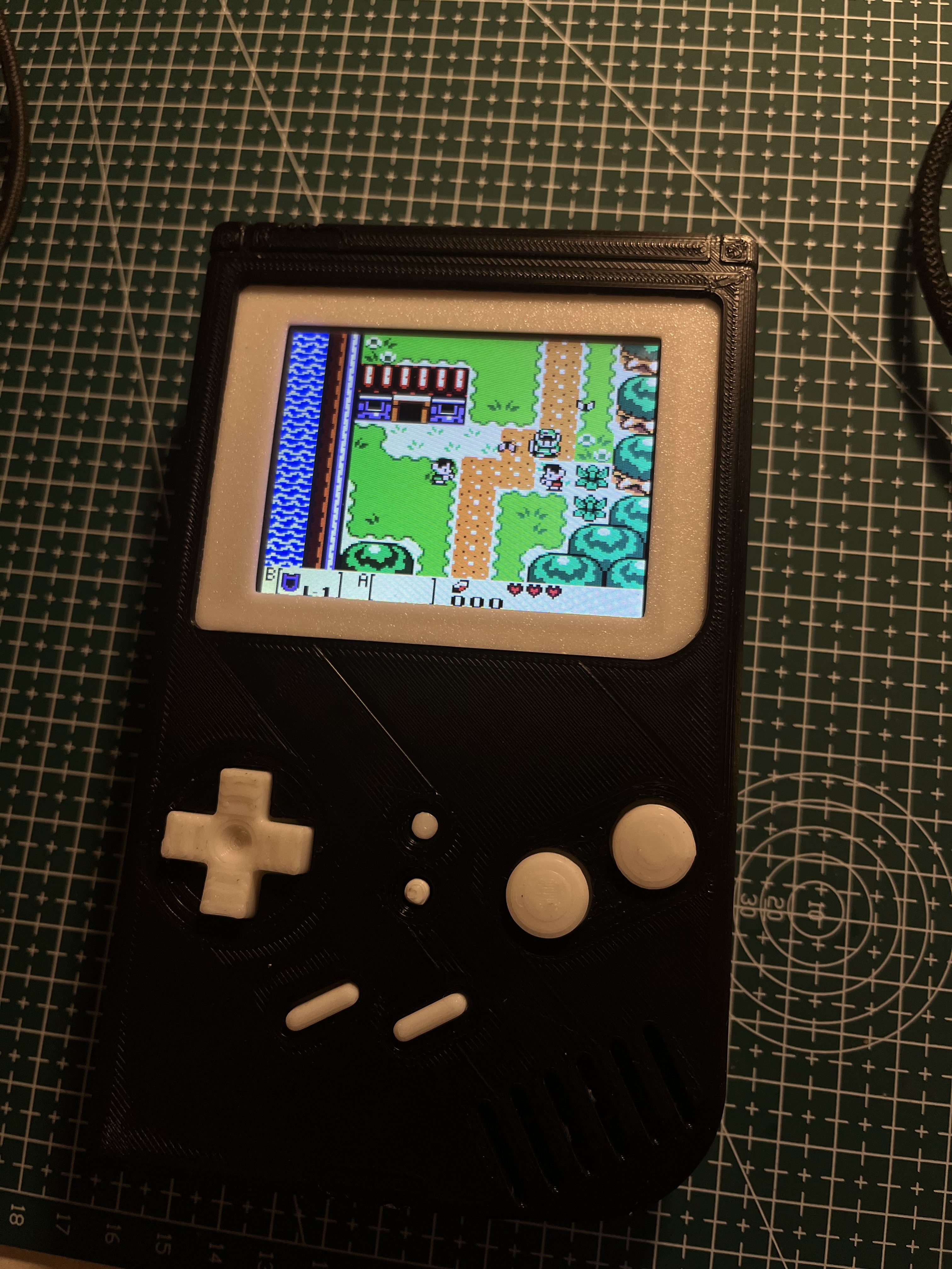
First run of the system:
Micro-controller
The core is the ESP32-S3-N16R8 — dual-core Xtensa LX7 at up to 240 MHz, with 16 MB of octal-SPI flash and 8 MB of octal-SPI PSRAM on the same package. Three properties made it the right fit for this workload:
Dual-core task pinning. Core 0 runs the emulator tick and audio mixing. Core 1 handles the display DMA transfer and input scanning. Separating these eliminates the scheduling jitter that causes audio glitches or dropped frames when everything competes on one timeline.
External PSRAM. On-chip SRAM is 512 KB — not enough to hold a 320×240 RGB565 framebuffer (150 KB) alongside ROM working memory. The 8 MB octal PSRAM, accessible at ~80 MHz via the dedicated MSPI bus, provides the headroom without requiring any swapping.
DMA-capable SPI. The SPI2 and SPI3 controllers support DMA-linked descriptor chains. A full frame transfer is triggered once and completes without CPU involvement — this is what makes 30+ FPS achievable without burning ISR time on frame pushes.
Power Supply + Charging Circuit
The power chain uses a two-stage conversion from an 18650 LiPo cell (3.7 V nominal, 3.0–4.2 V across the discharge curve):
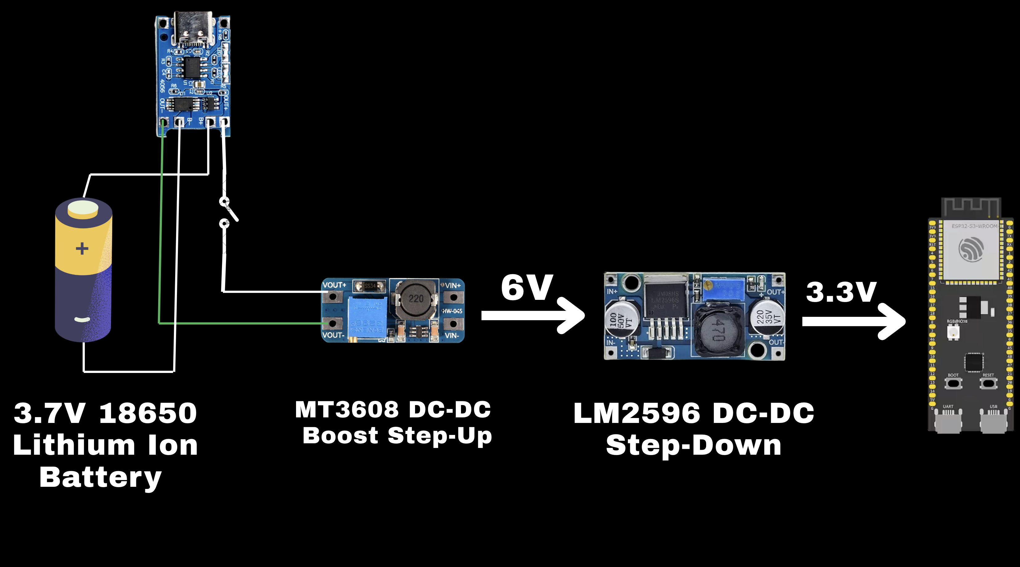
An MT3608 DC-DC boost converter first steps the battery voltage up to a fixed 6 V. That regulated 6 V then feeds an LM2596 DC-DC buck converter, which steps it down to a stable 3.3 V for the ESP32-S3 and all peripherals.
The reason for boost-then-buck rather than a direct buck from 3.7 V: a buck converter requires its input to be higher than its output by its dropout margin. As the 18650 discharges toward 3.0 V, a direct 3.7→3.3 V buck loses regulation and browns out the system. By boosting to 6 V first, the LM2596 always has sufficient headroom to hold 3.3 V flat across the entire battery life.
Charging is handled separately by a TP4056-based USB-C module that feeds the 18650 directly, independent of the boost converter. A power switch on the battery output line gates the rest of the circuit.
Case 3D Design + Buttons PCB
The enclosure was designed in 3D and printed to fit the exact component stack — display module, main board, battery, and button board — with cutouts for the screen, buttons, USB-C charging port, and power switch.
The button board is hand-soldered on perfboard. The D-pad uses a resistor ladder wired to two ADC channels (ADC1 CH5 and CH6): each direction pulls the line to a different voltage level, and the firmware distinguishes directions by comparing the ADC reading against defined min/max thresholds. Up and Down share CH5, Left and Right share CH6 — four directions multiplexed onto two ADC pins, saving GPIO.
Action buttons (A, B, Select, Start, Menu, Option) use standard GPIO lines with internal pull-ups. A pressed button pulls the pin low. The full input map is in config.h.

Audio Circuit
Audio is handled by a MAX98357A — an I2S input, Class-D mono amplifier that outputs directly to a speaker with no external components needed beyond decoupling capacitors. It accepts a standard I2S stream (BCK, WS, DATA) and handles the digital-to-analog conversion and amplification internally.
In Retro-Go, emulator cores push audio samples into a FreeRTOS ring buffer. A dedicated task drains the buffer into the I2S DMA TX FIFO, which feeds the MAX98357A. The ESP32-S3’s internal DAC is disabled (RG_AUDIO_USE_INT_DAC 0, RG_AUDIO_USE_EXT_DAC 1 in config.h). GPIO assignments are in the repo.
SD Card Reader + Screen
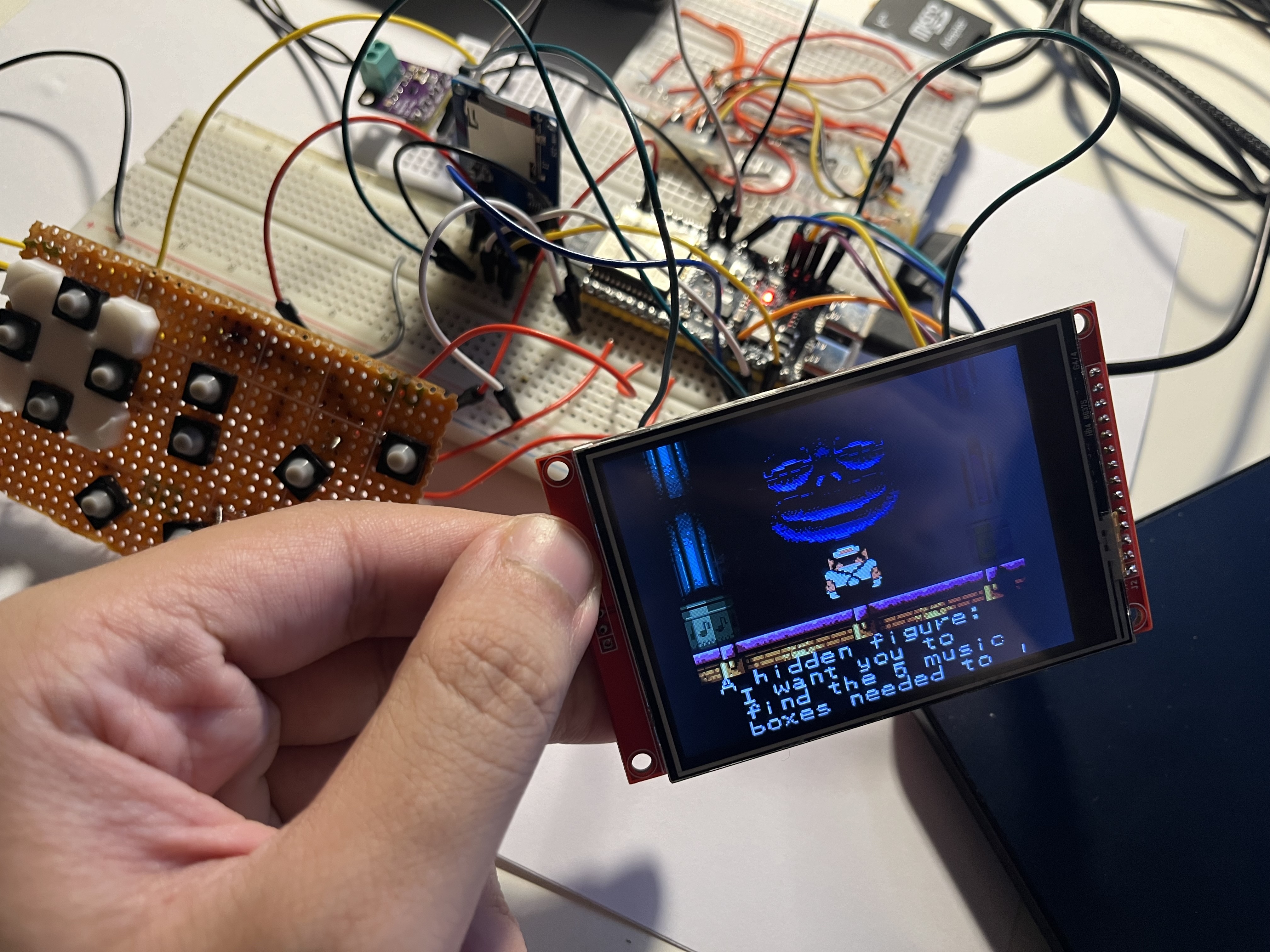
Screen. The display is a 3.2″ ILI9341 TFT module (320×240, RGB565) driven over SPI2 at 40 MHz with DMA. The emulator writes a completed frame into a PSRAM-backed framebuffer; a display task on Core 1 kicks off the DMA descriptor chain transfer; the DMA completion ISR signals Core 0 that the buffer is free — keeping frame pushes off the CPU entirely.
The display module was physically mounted inverted inside the enclosure, so the image came out upside down on first boot. Fixing this required setting RG_SCREEN_ROTATE 2 and writing the correct value to the ILI9341 MADCTL register in the init sequence:
ILI9341_CMD(0x36, 0xA8); // MADCTL: MY=1, MV=1, BGR=1 → 180° rotation
0xA8 = 10101000: bit 7 (MY) flips row order, bit 5 (MV) exchanges rows and columns, bit 3 (BGR) sets the color filter. The combination produces a 180° rotation with correct color output. The full RG_SCREEN_INIT() sequence covering power control, VCOM, frame rate, and gamma is in config.h.
SD card. The SD card module runs on SPI3 (separate host from the display), mounted as FAT32 via esp_vfs_fat_sdspi_mount at /sd. At boot the launcher enumerates /sd/roms, builds an in-memory title list grouped by system, and renders the menu. ROM data streams into PSRAM during emulator init rather than fully buffering at load time.
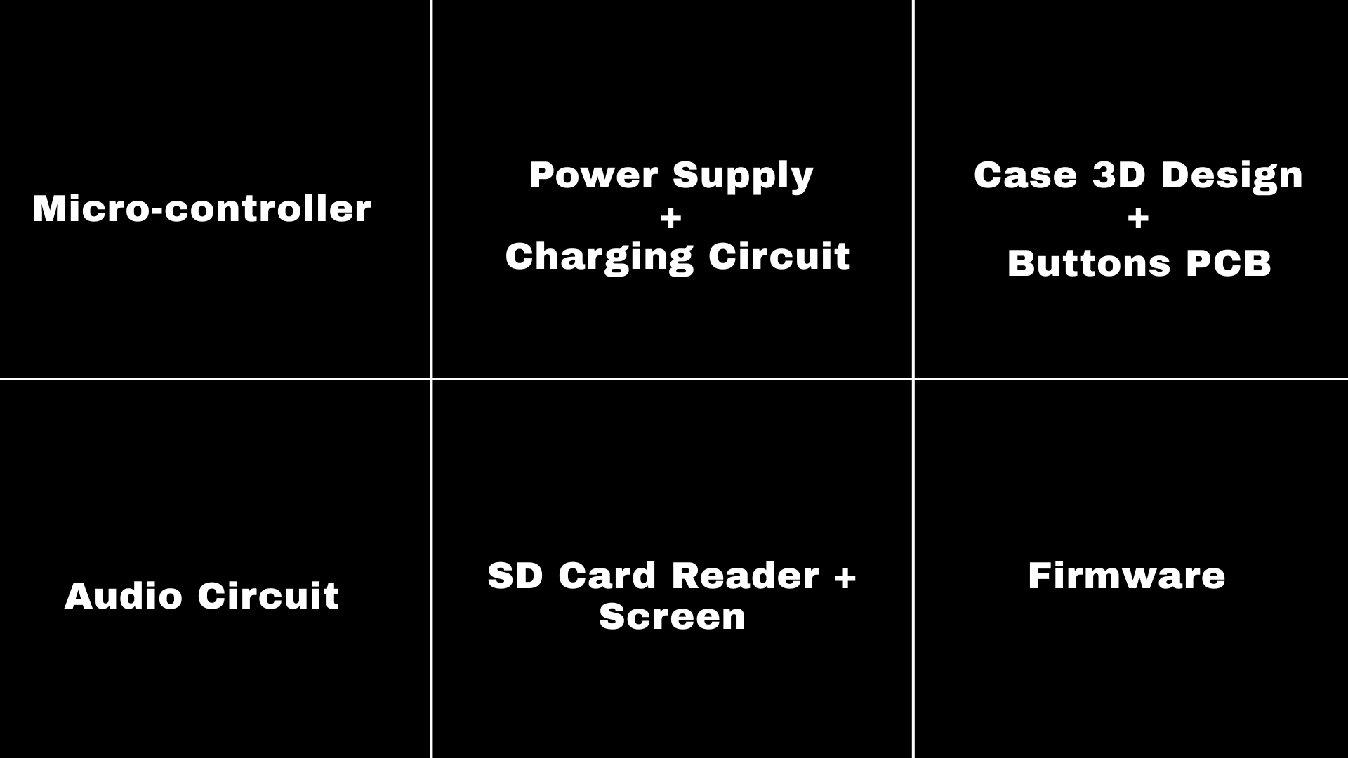
Firmware
Retro-Go is an ESP-IDF multi-emulator launcher that natively targets the ESP32 and ESP32-WROVER. The ESP32-S3 is not a supported target — its peripheral base addresses, GPIO matrix, PSRAM controller, and Kconfig surface all differ. There was no existing board file to adapt: the port meant writing config.h entirely from scratch and iterating until every subsystem came up correctly.
In Retro-Go, each hardware target is fully described by a single config.h — every GPIO assignment, bus host, SPI speed, display driver, input map, and init sequence lives there. Writing it required tracing every wire, identifying which ESP32-S3 GPIO each peripheral landed on, and encoding it into the correct macros. A wrong GPIO means the peripheral either does nothing or corrupts the bus — the first several builds produced a black screen, no SD mount, or silent audio, each pointing to a specific mismatch to trace and fix.
The full config.h is in the GitHub repo.
With all subsystems stable — display, input, storage, audio — the NES, Game Boy, and Sega Master System cores ran at full speed with no frame drops.
Engineering presentation and award
The project was submitted to the 20th NU Undergraduate Research Forum, Egypt’s largest national undergraduate research competition. The presentation covered the full system end-to-end: the power regulation chain, wiring and signal integrity, SPI/DMA pipeline architecture, HAL porting methodology, input debounce design, FAT filesystem integration, and PSRAM memory layout. Judges asked specifically about the boost-then-buck power decision and the DMA descriptor chain design — being able to explain the why behind each decision, not just that it worked, is what separated this from other embedded projects.

The full project — firmware source, wiring notes, and configuration — is open source.
GitHub repo: https://github.com/AshrafHanyy/GameBoy-ESP32-S3
Comments
comments powered by Disqus